
RESEARCH ARTICLE
Inertial Forces Acting on a Propeller of Aircraft
R. Usubamatov*, T. Zhumaev
Article Information

Identifiers and Pagination:
Year: 2018Volume: 7
First Page: 1
Last Page: 13
Publisher Id: TOAEJ-7-1
DOI: 10.2174/1874146001807010001
Article History:
Received Date: 12/4/2018Revision Received Date: 23/5/2018
Acceptance Date: 7/6/2018
Electronic publication date: 29/08/2018
Collection year: 2018
open-access license: This is an open access article distributed under the terms of the Creative Commons Attribution 4.0 International Public License (CC-BY 4.0), a copy of which is available at: (https://creativecommons.org/licenses/by/4.0/legalcode). This license permits unrestricted use, distribution, and reproduction in any medium, provided the original author and source are credited.
Abstract
Background:
Aerospace vehicles use propellers with the different design that possess gyroscopic properties. Recent investigations in the area of gyroscope theory have demonstrated that the gyroscope properties are based on the action of the centrifugal, common inertial, and Coriolis forces of the distributed mass elements of the spinning rotor, as well as the change in the angular momentum.
Objective:
The combined action of the interrelated inertial forces on the propellers presents the interests for the design of the blades. The objective of the manuscript is the derivation of mathematical models for the inertial torques acting on the spinning propellers that enable computing the stresses of the blades and increasing their reliability.
Method:
The inertial torques generated by the masses of the rotating blades acting on the propellers are represented by mathematical models in L. Euler’s form.
Results:
The inertial torques are generated by the several inertial forces of the propeller’s blades and hub and manifested the fluctuation of the variable resistance and precession torques acting around different axes of the propeller. Derived mathematical models for the inertial torques are new and should be used for the computing forces and stresses acting on the propellers of the aircraft.
Conclusion:
The mathematical models for the torques acting on the propellers consider the several inertial forces of the rotating masses that manifest their gyroscope properties. Derived mathematical models for inertial torques enable for computing the stresses of the aircraft propellers and clearly demonstrate the physical principles and origin of the acting inertial forces.
1. INTRODUCTION
Industrial Revolution involved scientists to pay the attention to the remarkable gyroscope property expressesed in permanent maintaining the axis of a spinning rotor in a space. Since those time brilliant, famous, outstanding, and ordinary scientists studied gyroscopic effects and published fundamental manuscripts that describe interesting gyroscope properties. The applied theory of gyroscope emerged mainly in the twentieth century due to increasing the angular velocities of the spinning components of the movable machines [1-4]. Numerous publications have been dedicated to computing of gyroscopic effects in engineering [5-7]. All fundamental textbooks of classical mechanics have chapters that represent gyroscope theory [8, 9]. There are many publications regarding gyroscope theory as well as many approaches and mathematical solutions that describe gyroscopic properties [10, 11]. However, all known manuscripts contain numerous assumptions, simplifications, as well as explaining the gyroscope effects in terms of the change in the angular momentum only [12-13]. Some researchers intuitively pointed to the action on the spinning rotor of other inertial forces [14, 15]. Nevertheless, the action of these inertial forces on gyroscopes is not presented by mathematical models.
Mathematical models for gyroscope properties in known publications do not match practical applications for gyroscopic devices [16, 17]. From this, researchers have spawned artificial terms, such as gyroscope effects and others that contradict the physics laws [18, 19]. This is the reason that gyroscope theory still attracts researchers seeking to find answers on gyroscope challenges [20, 21]. However, the origin of gyroscope effects is more complex than those represented in the known theories. Recent investigations of the physical principles of gyroscope motions demonstrating that the centrifugal, common inertial, Coriolis forces, and the change in the angular momentum manifest the action of gyroscope’s resistance and precession torques [22-24]. New mathematical models for inertial torques give significant impact to the gyroscope theory and enable for describing all gyroscope properties. This work considers the action of the inertial torques on the aircraft’s propeller with the different number of blades.
2. CENTRIFUGAL FORCES ACTING ON A PROPELLER
The typical design of an aircraft propeller is represented by the several blades mounted on the cylindrical hub that can be considered as the spinning rotor. The inertial forces acting on the propeller are generated by its centre mass of the hub and centre mass of the blades, whose locations and actions are different. The action of inertial forces is considered on a propeller running with a constant angular velocity of ω in a counterclockwise direction when viewed from the tip of axis oz (Fig. 1). The propeller blade’s centre mass m is located on the circle whose radius is r and the mass centre of the hub is mh. The blades numbered as I, II, III, IV, V, and VI.
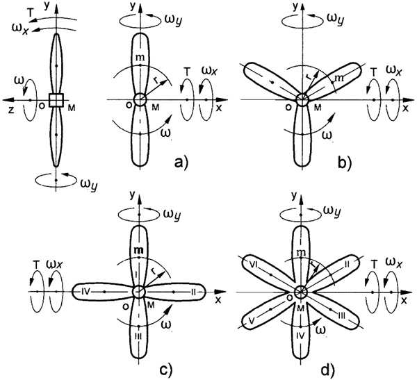 |
Fig. (1). Schematic of the propeller design with two (a), three (b), four (c) and six (d) blades. |
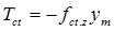
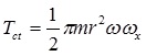
The mass moments of inertia for propellers with several blades are defined by the expression Jp = nJ + Jh, where J is the mass moments of inertia of the blade, n is the number of the blades, and Jh is the mass moments of inertia of the hub. The mathematical models for inertial torques generated by the mass of the propeller’s hub are the same as for the spinning disc [24]. The equations of the inertial torques generated by the blades are defined by the following approach. In uniform circular motions, the blade’s mass moves with acceleration that generates the centrifugal forces (Fig. 2). The inclination of the propeller plane on the small angle Δγ around axis ox leads to the change in the direction of the centrifugal force vector fct. The vector fct, in which the direction coincides with axis ox (i.e. located on 0o and 180o along axis ox), does not change. Other vectors fct are located on the inclined plane and have the non-identical change in their own directions. The maximal declination of the vector f*ct is at 90o and 270o from axis ox (Fig. 2). These variable directions of the centrifugal force vector generate the change in the vector’s components fct.z, whose direction is parallel to the axle oz. The vector of the centrifugal forces fct.z and its variable radius of location relative to axis ox generate the resistance torque Tct acting opposite to the torque T applied on the propeller. The resistance torque is expressed by the following equation:
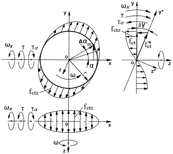 |
Fig. (2). Schematic of acting centrifugal forces, torques and motions of the spinning propeller’s blade. |
 |
(1) |
where Tct is the torque generated by the centrifugal force of the rotating blade’s mass, fct.z is the axial component of the centrifugal force; and ym = rsinα is the distance of the blade’s mass location in along axis oy, sign (-) means the action of the torque in the clockwise direction.
The equation of fct.z is represented by the following expression:
 |
(2) |
where fct = mrω2 is the centrifugal force of the blade’s mass m, ω is the angular velocity of the propeller, α is the angle of the blade’s mass location, Δγ is the angle of the propeller’s plane inclination (sinΔγ = Δγ for the small value of the angle), other parameters are as specified above.
Substituting the defined parameters into Eq. (1) yields the following equation:
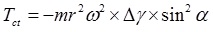 |
(3) |
Then replacing sin2α = (1/2)(1 - cos2α) that is the trigonometric identity and substituting into Eq. (3) yields the following equation:
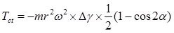 |
(4) |
The rate change in the torque Tct per time is represented by the following differential equation:
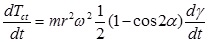 |
(5) |
where t = α/ω is the time has taken relative to the angular velocity of the propeller and other parameters are as expressed above
Then, the differential of time is:  while the expression
  is the angular velocity of the propeller precession around axis ox. Substituting obtained components into Eq. (5), transformation, separating variables and presenting in the integral form with defined limits the following equation emerges:
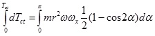 |
(6) |
Solving of Eq. (6) 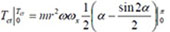 giving the following rise
 |
(7) |
The value of the resistance torque generated by the centrifugal forces of the rotating blade is changed by sinus law. The resistance torque acts on the upper and lower sides of the propeller with several blades. Then the total resistance torque Tct of the propellers (Figs. 1a-d) is increased according to the number n of blades and expressed by the following equation:
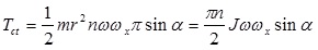 |
(8) |
where J = mr2 is the conventional mass moment of inertia of the propeller’s blade, n is the number of blades, other parameters are as specified above.
The change in the resistance torque Tct generated by the centrifugal forces of the propellers with n blades (Figs. 1a-d) is represented in Figs. (3a-d).
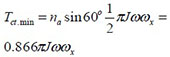
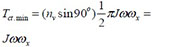
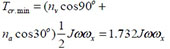
The equations for maximal and minimal values of the resistance torques for the propellers are represented in Table 1. The value of the resistance torque of the propeller depends on the following components:
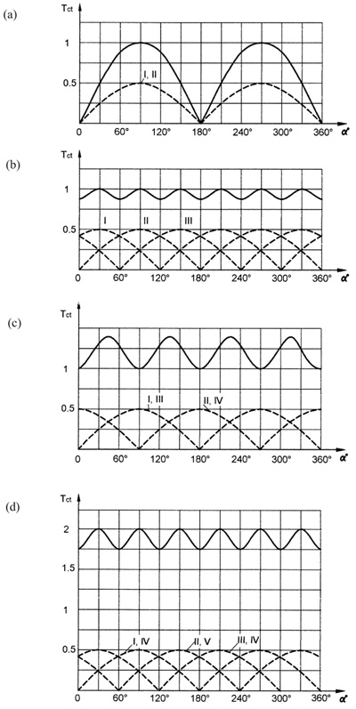 |
Fig. (3). The change in the resistance torque that generated by the propeller with two (a), three (b), four (c) and six (d) blades. |
| Number Blades, n |
Equation, Tct | Number of Blades Location | ||
|---|---|---|---|---|
| Vertical, nv | Horizontal, nh | Angular, ni |
||
| Two |  |
2 | 0 | 0 |
 |
0 | 2 | 0 | |
| Three | 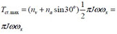 |
1 | 0 | 2 |
 |
0 | 1 | 2 | |
| Four | 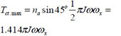 |
0 | 0 | 4 |
 |
2 | 2 | 0 | |
| Six | 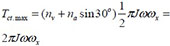 |
2 | 0 | 4 |
 |
0 | 2 | 4 | |
- The vertical, horizontal or angular location of the blades relative axis,
- The mass and the number of the blades,
- The radius of the location of the blade mass,
- The angular velocity of the propeller and
- The angular velocity of the precession.
3. INERTIAL FORCES ACTING ON A PROPELLER
The uniform circular motion of the propeller experiences the tangential velocity of the blade’s mass. Under the action of the external torque, a propeller turns around axis ox (Fig. 4) that leads to the non-identical change in the direction of the tangential velocity vectors. The maximal changes in direction have the velocity vectors V* of the blade’s mass located on the line of axis ox (Fig. 4). The two vectors V do not have any changes, whose direction is parallel to the line of axis ox, i.e. located on 90o and 270o. These variable directions on the tangential velocity vectors generate the change in the vector’s components Vz whose directions are parallel to the axle oz.
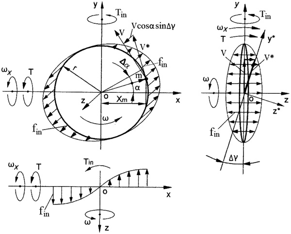 |
Fig. (4). Schematic of acting inertial forces, torques and motions of the spinning propeller. |
The change in the velocity vectors refers to the accelerated motions of the rotating blade’s mass that generate their inertial forces fin and the inertial torque Tin acting around axis oy that is expressed by the following equation:
 |
(9) |
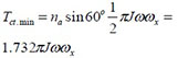
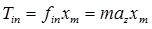
where Tin is the torque generated by the inertial force of propeller mass fin; az is the acceleration of the blade’s mass m along axis oz; and xm = rcosα is the distance to the mass location along axis ox; other components are represented in section 1.
The equation for the acceleration az of the blade’s mass element is defined by the first derivative of the change in the tangential velocity, whose value depends on the angle of its location that is variable with time.
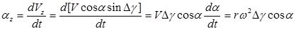 |
(10) |
where az = dVz/dt is the acceleration of the mass along axis oz; Vz = VcosαsinΔ γ is the change in the tangential velocity V of the mass; Δγ is the angle of the turn of the propeller’s plane around axis oy (sinΔγ = Δγ for the small values of the angle); V = rω, ω = dα/dt is the angular velocity of the spinning of propeller; α is the angular location of the blade’s mass; other parameters are as specified above.
Substituting the defined parameters into Eq. (10) yields the following equation:
 |
(11) |
Then, trigonometric identity  is substituted into Eq. (11) that is presented by the following equation:
 |
(12) |
Equation (12) is similar to Eq. (4) with the same final expression:
 |
(13) |
The value of the precession torque generated by the rotating blade is changed by cosine law and expressed by the following equation:
 |
(14) |
Equation (14) is similar to Eq. (8) with the difference in the trigonometric factor that is replaced by cosα. The total and maximal value of the precession torque acting around axis oy is represented as a sum of the precession torques generated by the inertial forces of the blade’s masses and the change in the angular momentum of the propeller’s hub, in which the expression is as follows:
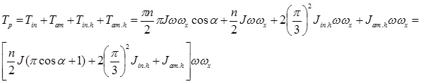 |
(15) |
where Tp is the precession torque,  is the torque generated by the centrifugal forces of the hub,
 is the torque generated by the change in the angular momentum of the hub [24], all parameters are as specified above.
Equation (15) is generic that enable defining the maximal and minimal values of the precession torques for the propellers based on equations of Table 1. The diagrams of the change in the value of the inertial torque Tin of the propeller with different blades are similar to the diagrams for the torque Tct generated by the centrifugal forces (Fig. 3). The differences are only the diagrams for inertial torques shifted on 90o along the abscissa.
4. CORIOLIS FORCES ACTING ON A PROPELLER
The action of the Coriolis acceleration and force is revealed on the propeller under the action of the external torque. Fig. (5) depicts the blade’s mass m that travels with the tangential velocity on the circle of the rotating propeller, which turns on the angle Δγ around axis ox. These motions of the mass produce the Coriolis acceleration and force. The turn of the propeller’s plane around axis ox leads to a non-identical change in the directions of the tangential velocity vectors of the mass. The maximal changes in the velocity vectors V* of the blade’s mass located on axis ox (Fig. 5). The vectors V, whose directions are parallel to axis ox, do not have changes. The variable directions of the tangential velocity vectors generate the change in the vector’s components Vz whose directions are parallel to the axle oz. The changes in the values of the velocity are expressed as an acceleration of the blade’s mass and their inertial forces.
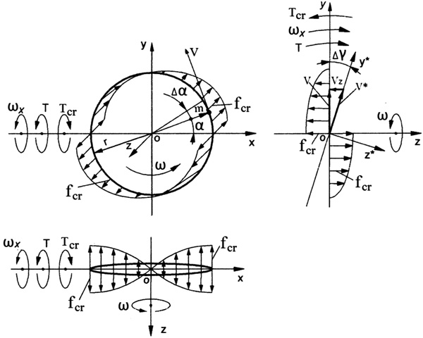 |
Fig. (5). Schematic of acting Coriolis forces, torques and motions of the spinning propeller’s blade. |
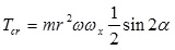
The resistance torque generated by the Coriolis force of the blade’s mass is expressed by the following equation:
 |
(16) |
where Tcr is the torque generated by Coriolis force fcr of the rotating blade’s mass m; az is the acceleration of the mass along axis oz; and ym = rsinα is the distance to the mass location along axis oy; the sign (-) means the action in the clockwise direction; other components are presented in Section 1.
The equation for Coriolis acceleration az of the blade’s mass is defined by the first derivative of the change in the tangential velocity, whose value depends on the angle of its location on the plane yoz that is variable at the time. The expression for az is represented by the following equation:
 |
(17) |
where Vz = VcosαsinΔγ(t) is the change in the tangential velocity V = rω of the blade’s mass; Δγ is the angle of turn of the propeller’s plane around axis ox (sinΔγ = Δγ for the small values of the angle); α is the angular location of the mass; ωx = Δγ/dt is the angular velocity of precession around axis ox; other parameters are as specified above.
Substituting defined parameters into Eq. (16) and transformation yields the following equation:
 |
(18) |
Fig. 5 depicts the locations of Coriolis forces of the mass m around axes oz and ox. Substituting the defined parameters into Eq. (18) and transformation yields the following equation:
 |
(19) |
Substituting the trigonometric identity  into Eq. (19) yields the following equation:
 |
(20) |
The rate change in the torque Tcr per time is represented by the following differential equation:
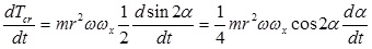 |
(21) |
where t = α/ω is the time taken relative to the angular velocity of the rotating blade, and other parameters are as expressed above.
Then, the differential of time is: while the expression  is the angular velocity of the rotating blade. Substituting defined components into Eq. (21), transformation, separating variables and presentation in the integral form with limits of the circle’s quarter yield the following equation:
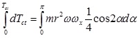 |
(22) |
Solving Eq. (3.104) yields the following result:
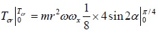 |
(23) |
where the change in the limits of integration for the centroid is taken for the quarter of the circle because its location at other quarters is the same.
Solving of Eq. (23):
 giving the following rise:
 |
(24) |
The value of Coriolis torque generated by the rotating blade is changed by cosine law and expressed by the following equation:
 |
(25) |
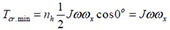
The equations for maximal and minimal values of Coriolis torques for the propellers are represented in Table 2.
| Number Blades, n |
Equation, Tcr | Number of Blades Location | ||
|---|---|---|---|---|
| Vertical, nv | Horizontal, nh | Angular, ni |
||
| Two |  |
0 | 2 | 0 |
 |
2 | 0 | 0 | |
| Three | 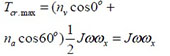 |
1 | 0 | 2 |
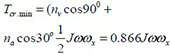 |
1 | 0 | 2 | |
| Four | |
0 | 0 | 4 |
 |
2 | 2 | 0 | |
| Six | 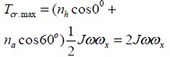 |
0 | 2 | 4 |
 |
2 | 0 | 4 | |
The diagrams of the change in the value of Coriolis torque Tcr acting on the propeller with different blades are similar to the diagrams for the centrifugal torque Tct (Fig. 3). The differences are only the diagrams for Coriolis torques shifted on 90o along the abscissa and values are less on the factor π according to Eqs. (8) and (26), respectively.
The total value of the resistance torque acting around axis ox is represented as a sum of the resistance torques generated by the centrifugal and Coriolis forces of the blade’s mass and propeller’s hub.
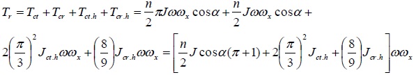 |
(26) |
where Tr is the resistance torque, Tct.h and Tcr.h is the resistance torques of centrifugal and Coriolis forces, respectively generated by the propeller’s hub, Jct.h = 2(π/3)2Jh and Jcr.h = (8/9)Jh is their factored mass moment of inertia [24], all other parameters are as specified above.
5. RESULTS AND DISCUSSION
In engineering propellers of an aircraft and ships manifest gyroscopic properties. The formulated mathematical models for the inertial torques acting on propellers with different designs are distinguished and proportionally depend on the number of blades, their mass moment of inertia and the angular velocity, as well as the angular velocity of its precession. The inertial torques are generated by the centrifugal, Coriolis and common inertial forces as well as the change in the angular momentum of the propeller’s blades and hub, and manifest the fluctuated and variable resistance and precession torques acting around different axes of the propeller. The derived mathematical models of the inertial torques are new and should be used for the computing of forces acting on a propeller aircraft.
CONCLUSION
The gyroscope theory is one of the most complex and intricate in terms of analytical solutions. The known mathematical models for gyroscope effects do not match adequately the practical tests and for engineering problem the complex numerical modeling is used. The new mathematical models for the torques acting on the aircraft’s propeller consider the several inertial forces of the rotating blade’s mass and propeller’s hub that manifest the gyroscope properties. Derived mathematical models for inertial propeller’s torques enable for solving problems relating to gyroscopic devices and clearly demonstrate the physical principles of the acting forces and motions.
LIST OF ABBREVIATIONS
| a | = Linear acceleration |
| fct, f cr., fin. | = Centrifugal, Coriolis and inertial forces, respectively, generated by blades mass of a spinning propeller |
| J | = Mass moment of inertia of a propeller’s blade |
| Jh | = Mass moment of inertia of a propeller’s hub |
| m | = Mass of a propeller’s blade |
| mh | = Mass of a propeller’s hub |
| n | = Number of propeller’s blade |
| r | = Radius of a location of a propeller’s blade mass |
| T | = Load external torque |
| Tct, Tcr., Tin. Tam – | = Torque generated by centrifugal Coriolis and inertial forces and a change in the angular momentum, respectively |
| Ti.max and Ti.min | = Maximal and minimal torques, respectively |
| t | = Time |
| V | = Linear velocity |
| xm, ym | = Centroid and distance of location of blade’s mass along axis ox and oy |
| Δα, α | = Increment angle and angle of the turn for a propeller around own axis, respectively |
| Δγ | = Angle of inclination of a propeller’s plane |
| ω | = Angular velocity of a propeller |
| ωx, | = Angular velocity of precession around axes ox |
CONSENT FOR PUBLICATION
Not applicable.
CONFLICT OF INTEREST
The authors declare no conflict of interest, financial or otherwise.
ACKNOWLEDGEMENT
This work is supported by the Kyrgyz State Technical University named after I. Razzakov, Kyrgyzstan.